The Arduino Uno makes serial communication with digital potentiometers (digipots) such as the Microchip MCP4241-103E/P, relatively easy.
The MCP4241-103E/p is available at www.mouser.com in through hole technology which makes experimenting a little more easy.
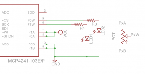
Here are what the the digipots look like inside the IC.
There are the typical three terminals to a regular pot available on the IC. I am using the center wiper to control the voltage to the anode of the LED. Resistors R3 and R4 can be 470 ohm to current limit the LED. The MCP4241 can source 25mA of current on any output pin, such as the wiper.
The first order of business is the code. Here is some code I modified that runs two LEDs through a range of voltages by connecting the anode of each to the wiper of the digipot.
/*
Digital Pot Control
Based on the original sketch for AD5206….
and based on the Version for MCP42xx April 2013, Jim Brown,
This example controls a Microchip digital potentiometer.
The MCP4241 has 2 potentiometer channels. Each channel’s pins are labeled
PAx – connect this to voltage
PWx – this is the pot’s wiper, which changes when you set it
PBx – connect this to ground.
The MCP4241 is SPI-compatible,and to command it, you send two bytes:
*** Here is where my analysis changes from Mr. Brown’s ***
8 bit Command: *see page 45 of the MCP4241 data sheet*
A=address, C=Command bit, D=data
AAAACCDD
I chose for AAAA 00h for Volatile Wiper 0 and then 01h for wiper 1
Command bits for both were Write Data so CC is 00
Data bit D9 is not used. D8 is zero, I have a 7bit reistor resolution.
So,
AAAACCDD is 00000000 to Write to Wiper 0 and 00010000 to Write to Wiper 1
The decimal values are 0 and 16 for CommandByte in the code below.
I swing the resistance value with the Data byte in my example from 0 to 80h or 0-127 because I use a 7 bit pot.
The circuit:
* All PA pins of MCP4241 connected to +5V
* All PB pins of MCP4241 connected to ground
* An LED and a 390-ohm resisor in series connected from each PW pin to ground
* CS – to digital pin 10 (SS pin)
* SI – to digital pin 11 (MOSI pin)
* SCK – to digital pin 13 (SCK pin)
Written November 29, 2014 with big thanks to the above mentioned people.
Robert Keeley
*/
// include the SPI library:
#include <SPI.h>
// set pin 10 as the slave select for the digital pot:
const int slaveSelectPin = 10;
void setup() {
// set the slaveSelectPin as an output:
pinMode (slaveSelectPin, OUTPUT);
// initialize SPI:
SPI.begin();
}
void loop() {
// go through Pot 1 first then Pot 2, CommandByte = 16 and then CommandByte = 0:
digitalPotWrite(0, 0); //turn off Pot 0 so it doesn’t float, partially lit:
delay(10);
int CommandByte = 16; // to Write to Pot 1
// change the resistance on this pot from min to max:
for (int level = 0; level < 127; level++) {
digitalPotWrite(CommandByte, level);
delay(10);
}
// wait at the top:
delay(100);
// change the resistance on this channel from max to min:
for (int level = 0; level < 127; level++) {
digitalPotWrite(CommandByte, 127 – level);
delay(10);
}
digitalPotWrite(16, 0); //make sure Pot 1 is off:
delay(10);
CommandByte = 0; // to Write to Pot 0
// change the resistance on this pot from min to max:
for (int level = 0; level < 127; level++) {
digitalPotWrite(CommandByte, level);
delay(10);
}
// wait at the top:
delay(100);
// change the resistance on this channel from max to min:
for (int level = 0; level < 127; level++) {
digitalPotWrite(CommandByte, 127 – level);
delay(10);
}
}
int digitalPotWrite(int CommandByte, int value) {
// take the SS pin low to select the chip:
digitalWrite(slaveSelectPin,LOW);
// send in the address and value via SPI:
SPI.transfer(CommandByte);
SPI.transfer(value);
// take the SS pin high to de-select the chip:
digitalWrite(slaveSelectPin,HIGH);
}
Here is a simple version of the schematic:
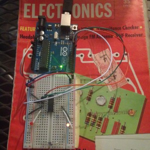
Working Circuit:
To Convert Analog Pot to Digipot Value:
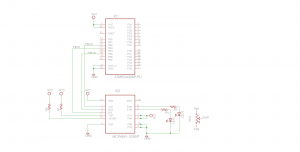
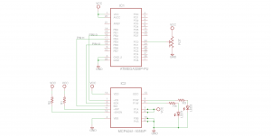
Here’s the schematic using the ADC of the Arduino to read the analog pot and the SPI connection to the MCP4241 to control LED voltage using the internal digital potentiometer:
Here is a simple method to take the analog pot and convert it to something the MCP4241 will accept. Note with an 8 bit pot I would have divided the variable potValue by 4 instead of 8.
CODE FOR ARDUINO
/*
Analog Pot Read for Digital Pot Control
Written November 30, 2014
Robert Keeley
*/
// include the SPI library:
#include <SPI.h>
const int slaveSelectPin = 10; // set pin 10 as the slave select for the digital pot:
float valueAnalogPot; // potValue divided by 8. 1024 values/128 7 bit resistor resolution:
int digiPotData; // value of analog pot scaled and cast into an integer:
void setup() {
pinMode (slaveSelectPin, OUTPUT); // set the slaveSelectPin as an output:
SPI.begin(); // initialize SPI:
Serial.begin(9600); //serial communication to screen:
// turn pots off, when the 4241 powers up it may float to a wiper value and LED will be partially lit:
digitalPotWrite(0, 0);
delay(1);
digitalPotWrite(16, 0);
delay(1);
}
void loop() {
int potValue = analogRead(A0); //store ADC of pot value 0-1023 in potValue:
Serial.println(potValue); //print value between 0-1023 to screen int datatype:
delay(1); //stability
valueAnalogPot = potValue/8; // scaled to fit 7 bit pot:
digiPotData = (int) valueAnalogPot; //cast to integer to be used as data byte for digipot
int CommandByte = 0; // Pot 0 – Write Mode:
// change the resistance on this digital pot 0 to scaled version of the analog pot:
digitalPotWrite(CommandByte, digiPotData);
delay(1);
}
int digitalPotWrite(int CommandByte, int value) {
// take the SS pin low to select the chip:
digitalWrite(slaveSelectPin,LOW);
// send in the address and value via SPI:
SPI.transfer(CommandByte);
SPI.transfer(value);
// take the SS pin high to de-select the chip:
digitalWrite(slaveSelectPin,HIGH);
}
The code now uses the analog input A(0) of the Arduino to read the analog pot and send a scaled version of it to the MCP4241 digital potentiometer.
Here’s a little video:


