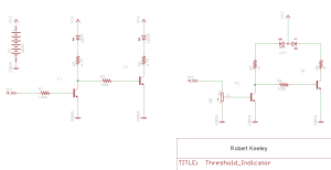
This is a simple threshold LED indicator circuit schematic and board. This was developed to work with our Keeley Bassist Compressor as a threshold indicator circuit. After working with comparator circuits over the years I have came to one conclusion; comparator IC’s draw too much current and make noise in audio circuits. After talking with my friend Jack Orman he pointed me in this direction. We were able to come out of the RMS detector circuit in the THAT Corp 4320 and go to our threshold detector.
How it works?
Think of these transistors as inverters. The base is the input and the collector the output.
A positive or high voltage on the base of T3 turns that transistor on and brings the collector low. With T3 on, the collector and emitter are essentially shorted and current will flow through the green LED and R7.
The low voltage on the collector of T3 is applied to the base of T4 and subsequently that transistor is off. That leaves the collector of T4 floating high. The red LED is off.
Likewise, apply a low voltage to the base of T3, T3 will turn off, and the collector will go high. That high is applied through R6 to the base of T4 and that turns the transistor on. Collector can be thought of as shorted to ground and the red LED turns on. (Lower R8 to 390-470 ohms so that the Red LED turns on a little brighter.)
It doesn’t work as perfectly as one might like because leakage currents will lead to both LEDs being on for a small voltage range but it performs well enough for the people I work with. 😉
R5 allows you to fine tune your threshold indicator circuit to toggle LED colors at the voltage you desire.
These types of circuits work will with PICs and other types of outputs where you might want an indicator circuit to trigger at a specific voltage.
Robert Keeley


